| Skip Navigation Links | |
| Exit Print View | |

|
Managing Oracle Solaris 11.1 Network Performance Oracle Solaris 11.1 Information Library |
| Skip Navigation Links | |
| Exit Print View | |

|
Managing Oracle Solaris 11.1 Network Performance Oracle Solaris 11.1 Information Library |
1. Introduction to Network Performance Management
Administering Link Aggregations
How to Create a Link Aggregation
How to Switch Between Link Aggregation Types
How to Modify a Trunk Aggregation
How to Add a Link to an Aggregation
How to Remove a Link From an Aggregation
How to Delete a Link Aggregation
4. Administering Bridged Networks (Tasks)
7. Exchanging Network Connectivity Information With LLDP
8. Working With Data Center Bridging Features in Oracle Solaris
9. Edge Virtual Bridging in Oracle Solaris
10. Integrated Load Balancer (Overview)
11. Configuring Integrated Load Balancer
12. Managing Integrated Load Balancer
13. Virtual Router Redundancy Protocol (Overview)
A. Link Aggregation Types: Feature Comparison
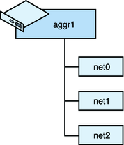
Link aggregation, also referred to as trunking, consists of several interfaces on a system that are configured together as a single, logical unit to increase throughput of network traffic. The following figure shows an example of a link aggregation configured on a system.
Figure 2-1 Link Aggregation Configuration

Figure 2-1 shows an aggregation aggr1 that consists of three underlying datalinks,net0 through net2. These datalinks are dedicated to serving the traffic that traverses the system through the aggregation. The underlying links are hidden from external applications. Instead, the logical datalink aggr1 is accessible.
Link aggregation has the following features:
Increased bandwidth – The capacity of multiple links is combined into one logical link.
Automatic failover and failback – By supporting link-based failure detection, traffic from a failed link is failed over to other working links in the aggregation.
Improved administration – All underlying links are administered as a single unit.
Less drain on the network address pool – The entire aggregation can be assigned one IP address.
Link protection – You can configure the datalink property that enables link protection for packets flowing through the aggregation.
Resource management – Datalink properties for network resources as well as flow definitions enable you to regulate applications' use of network resources. For more information about resource management, see Chapter 3, Managing Network Resources in Oracle Solaris, in Using Virtual Networks in Oracle Solaris 11.1.
Note - Link aggregations perform similar functions as IP multipathing (IPMP) to improve network performance and availability. For a comparison of these two technologies, see Appendix B, Link Aggregations and IPMP: Feature Comparison.
Oracle Solaris supports two types of link aggregations:
Trunk aggregations
Datalink multipathing (DLMP) aggregations
For a quick view of the differences between these two types of link aggregations, see Appendix A, Link Aggregation Types: Feature Comparison.
The following sections describe each type of link aggregation in greater detail.
Trunk aggregation benefits a variety of networks with different traffic loads. For example, if a system in the network runs applications with distributed heavy traffic, you can dedicate a trunk aggregation to that application's traffic to avail of the increased bandwidth. For sites with limited IP address space that nevertheless require large amounts of bandwidth, you need only one IP address for a large aggregation of interfaces. For sites that need to hide the existence of internal interfaces, the IP address of the aggregation hides its interfaces from external applications.
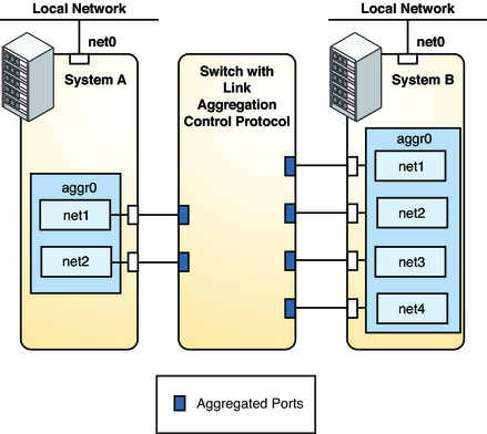
In Oracle Solaris, trunk aggregations are configured by default when you create an aggregation. Typically, systems that are configured with link aggregations also use an external switch to connect to other systems. See the following figure.
Figure 2-2 Link Aggregation Using a Switch

Figure 2-2 depicts a local network with two systems, and each system has an aggregation configured. The two systems are connected by a switch on which link aggregation control protocol (LACP) is configured.
System A has an aggregation that consists of two interfaces, net1 and net2. These interfaces are connected to the switch through aggregated ports. System B has an aggregation of four interfaces, net1 through net4. These interfaces are also connected to aggregated ports on the switch.
In this link aggregation topology, the switch must support aggregation technology. Accordingly, its switch ports must be configured to manage the traffic from the systems.
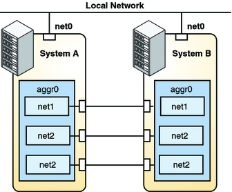
Trunk aggregations also supports back-to-back configuration. Instead of using a switch, two systems are directly connected together to run parallel aggregations, as shown in the following figure.
Figure 2-3 Back-to-Back Link Aggregation Configuration

Figure 2-3 shows link aggregation aggr0 on System A directly connected to link aggregation aggr0 on System B by means of the corresponding links between their respective underlying datalinks. In this way, Systems A and B provide redundancy and high availability, as well as high-speed communications between both systems. Each system also has net0 configured for traffic flow within the local network.
The most common application for back-to-back link aggregations is the configuration of mirrored database servers. Both servers must be updated together and therefore require significant bandwidth, high-speed traffic flow, and reliability. The most common use of back-to-back link aggregations is in data centers.
Note - Back-to-back configurations are not supported on DLMP aggregations.
The following sections describe other features that are unique to trunk aggregations. Do not configure these features when creating DLMP aggregations.
If you plan to use a trunk aggregation, consider defining a policy for outgoing traffic. This policy can specify how you want packets to be distributed across the available links of an aggregation, thus establishing load balancing. The following are the possible layer specifiers and their significance for the aggregation policy:
L2 – Determines the outgoing link by hashing the MAC (L2) header of each packet
L3 – Determines the outgoing link by hashing the IP (L3) header of each packet
L4 – Determines the outgoing link by hashing the TCP, UDP, or other ULP (L4) header of each packet
Any combination of these policies is also valid. The default policy is L4.
If your setup of a trunk aggregation includes a switch, you must note whether the switch supports LACP. If the switch supports LACP, you must configure LACP for the switch and the aggregation. The aggregation's LACP can be set to one of three values:
off – The default mode for aggregations. LACP packets, which are called LACPDUs are not generated.
active – The system generates LACPDUs at regular intervals, which you can specify.
passive – The system generates an LACPDU only when it receives an LACPDU from the switch. When both the aggregation and the switch are configured in passive mode, they cannot exchange LACPDUs.
A trunk aggregation generally suffices for the requirements of a network setup. However, a trunk aggregation is limited to work with only one switch. Thus, the switch becomes a single point of failure for the system's aggregation. Past solutions to enable aggregations to span multiple switches present their own disadvantages:
Solutions that are implemented on the switches are vendor-specific and not standardized. If multiple switches from different vendors are used, one vendor's solution might not apply to the products of the other vendors.
Combining link aggregations with IP multipathing (IPMP) is very complex, especially in the context of network virtualization that involves global zones and non-global zones. The complexity increases as you scale the configurations, for example, in a scenario that includes large numbers of systems, zones, NICs, virtual NICs (VNICs), and IPMP groups. This solution would also require you to perform configurations on both the global zone and every non-global zone on every system.
Even if a combination of link aggregation and IPMP is implemented, that configuration does not benefit from other advantages of working on the link layer alone, such as link protection, user-defined flows, and the ability to customize link properties such as bandwidth.
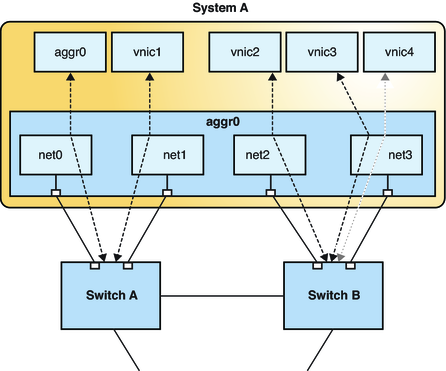
DLMP aggregations overcome these disadvantages. The following figure shows how a DLMP aggregation works.
Figure 2-4 DLMP Aggregation

Figure 2-4 shows System A with link aggregation aggr0. The aggregation consists of four underlying links, from net0 to net3. In addition to aggr0, the primary interface, VNICs are also configured over the aggregation: vnic1 through vnic4. The aggregation is connected to Switch A and Switch B which, in turn, connect to other destination systems in the wider network.
In a trunk aggregation, every port is associated with every configured datalink over the aggregation. In a DLMP aggregation, a port is associated with any of the aggregation's configured datalinks as well as with the primary the interface and VNICs over that aggregation.
If the number of VNICs exceeds the number of underlying links, then an individual port is associated with multiple datalinks. As an example, Figure 2-4 shows that vnic4 shares a port with vnic3.
Similarly, if an aggregation's port fails, then all the datalinks that use that port are distributed among the other ports. For example, if net0 fails, then aggr0 will share a port with one of the other datalinks. The distribution among the aggregation ports occurs transparently to the user and independently of the external switches connected to the aggregation.
If a switch fails, the aggregation continues to provide connectivity to its datalinks by using the other switches. A DLMP aggregation can therefore use multiple switches.
In summary, DLMP aggregations support the following features:
The aggregation can span multiple switches.
No switch configuration is required nor must be performed on the switches.
You can switch between a trunk aggregation and a DLMP aggregation by using the dladm modify-aggr command, provided that you use only the options supported by the specific type.
Note - If you switch from a trunk aggregation to a DLMP aggregation, you must remove the switch configuration that was previously created for the trunk aggregation.
Your link aggregation configuration is bound by the following requirements:
No IP interface must be configured over the datalinks that will be configured into an aggregation.
All the datalinks in the aggregation must run at the same speed and in full-duplex mode.
For DLMP aggregations, you must have at least one switch to connect the aggregation to the ports in other systems. You cannot use a back-to-back setup when configuring DLMP aggregations.
On SPARC based systems, each datalink must have its own unique MAC address. For instructions, refer to How to Ensure That the MAC Address of Each Interface Is Unique in Connecting Systems Using Fixed Network Configuration in Oracle Solaris 11.1.
Devices must support link state notification as defined in the IEEE 802.3ad Link Aggregation Standard in order for a port to attach to an aggregation or to detach from an aggregation. Devices that do not support link state notification can be aggregated only by using the -f option of the dladm create-aggr command. For such devices, the link state is always reported as UP. For information about the use of the -f option, see How to Create a Link Aggregation.