| Skip Navigation Links | |
| Exit Print View | |

|
Managing Oracle Solaris 11.1 Network Performance Oracle Solaris 11.1 Information Library |
| Skip Navigation Links | |
| Exit Print View | |

|
Managing Oracle Solaris 11.1 Network Performance Oracle Solaris 11.1 Information Library |
1. Introduction to Network Performance Management
4. Administering Bridged Networks (Tasks)
7. Exchanging Network Connectivity Information With LLDP
8. Working With Data Center Bridging Features in Oracle Solaris
9. Edge Virtual Bridging in Oracle Solaris
10. Integrated Load Balancer (Overview)
11. Configuring Integrated Load Balancer
12. Managing Integrated Load Balancer
13. Virtual Router Redundancy Protocol (Overview)
Using VRRP in Local Area Network
Administering VRRP Subcommands
Displaying the Configuration of a Router
Inter-operations With Other Network Features
A. Link Aggregation Types: Feature Comparison
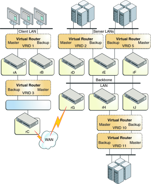
The following figure shows how VRRP works. The text that follows the figure explains the VRRP components that are used in the figure.
Figure 13-1 Working of VRRP

In the preceding figure, VRRP uses the following components:
Router rA is the master router for virtual router VRID 1 and the backup router for VRID 3. Router rA handles the routing of packets that are addressed to the VIP for VRID 1 and is ready to assume the routing role for VRID 3.
Router rB is the master router for virtual router VRID 3 and the backup router for VRID 1. Router rB handles the routing of packets that are addressed to the VIP for VRID 3 and is ready to assume the routing role for VRID 1.
Router rC does not have VRRP functions, but it uses the VIP for VRID 3 to reach the client LAN subnet.
Router rD is the master router for VRID 2. Router rF is the master router for VRID 5. Router rE is the backup router for both of these VRIDs. If rD or rF fails, rE becomes the master router for that VRID. Both rD and rF could fail at the same time. The fact that a VRRP router is a master router for one VRID does not preclude it from being a master router for another VRID.
Router rG is the wide area network (WAN) gateway for the backbone LAN. All of the routers attached to the backbone are sharing routing information with the routers on the WAN by using a dynamic routing protocol such as Open Shortest Path First (OSPF). VRRP is not involved in this aspect, although router rC advertises that the path to the client LAN subnet is through the VIP of VRID 3.
Router rH is the master router for VRID 10 and the backup router for VRID 11. Likewise, router rJ is the master router for VRID 11 and the backup router for VRID 10. This VRRP load-sharing configuration illustrates that multiple VRIDs can exist on a single router interface.
VRRP can be used as part of a network design that provides almost total routing redundancy for all systems on the network.