| Skip Navigation Links | |
| Exit Print View | |

|
Introduction to Oracle Solaris 11 Networking Oracle Solaris 11.1 Information Library |
| Skip Navigation Links | |
| Exit Print View | |

|
Introduction to Oracle Solaris 11 Networking Oracle Solaris 11.1 Information Library |
1. Networking on Oracle Solaris 11 Systems
Network Configuration Profiles
Reactive Network Configuration
Network Devices and Datalink Names
Assignment of Generic Names to Datalinks
Customizing How Generic Link Names Are Assigned By the Operating System
Link Names on Upgraded Systems
Replacing Hardware-Based Link Names
Network interfaces provide the connection between the system and the network. These interfaces are configured over datalinks, which in turn correspond to instances of hardware devices on the system. Network hardware devices are also called network interface cards (NICs) or network adapters. NICs can be built in and already present on the system when the system is purchased. However, you can also purchase separate NICs to add to the system. Certain NICs have only a single interface that resides on the card. Other brands might have multiple interfaces that you can configure to perform network operations.
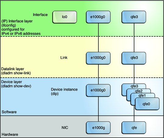
In previous Oracle Solaris implementations of the network stack, interfaces and links on the software layer build on the devices in the hardware layer. More specifically, a hardware device instance in the hardware layer has a corresponding link on the datalink layer and a configured interface on the interface layer. This one-to-one relationship among the network device, its datalink, and the IP interface is illustrated in the figure that follows.
Figure 1-1 Network Stack Showing Network Devices, Links, and Interfaces — Previous Oracle Solaris Implementation

Figure 1-1 shows two NICs on the hardware layer: e1000 with a single device instance e1000g0, and qfe with multiple device instances, qfe0 to qfe3. The devices qfe0 through qfe2 are not used. Devices e1000g and qfe3 are used and have corresponding links e1000g and qfe3 on the datalink layer. In the figure, the IP interfaces are likewise named after their respective underlying hardware, e1000g and qfe3. These interfaces can be configured with IPv4 or IPv6 addresses to host both types of network traffic. Note also the presence of the loopback interface lo0 on the interface layer. This interface is used to test, for example, that the IP stack is functioning properly.
Different administrative commands are used at each layer of the stack. For example, the dladm show-dev command lists hardware devices that are installed on the system. The dladm show-link command lists information about links on the datalink layer. The ifconfig command shows the IP interface configuration on the interface layer.
In this model, a one-to-one relationship exists that binds the device, the datalink, and the interface. This relationship means that network configuration is dependent on hardware configuration and network topology. Interfaces must be reconfigured if changes are implemented in the hardware layer, such as replacing the NIC or changing the network topology.
In Oracle Solaris 11, the one-to-one relationship between the hardware, datalink, and interface layers remains. However, the software layer is decoupled from the hardware layer. With this separation, network configuration on the software level is no longer bound to the chipset or the network topology in the hardware layer. This implementation makes network administration more flexible in the following ways:
The network configuration is insulated from any changes that might occur in the hardware layer. Link and interface configurations are preserved even if the underlying hardware is removed. These same configurations can then be reapplied to any replacement NIC, provided that the two NICs are of the same type.
The separation of the network configuration from the network hardware configuration also allows the use of customized link names in the datalink layer.
With the abstraction of the datalink layer, multiple networking abstractions or configurations such as VLANs, VNICs, physical devices, link aggregations, and IP tunnels are unified into a common administrative entity, which is the datalink.
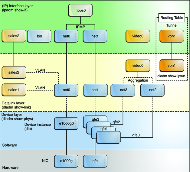
The following figure shows the interrelationship among devices, link types, and their corresponding interfaces.
Figure 1-2 Network Stack Showing Network Devices, Links, and Interfaces — Oracle Solaris 11 Implementation

Note - In the figure, the datalinks are named according to specific functions that they perform on the system, such as video0 or sales2. The figure highlights the flexibility with which you can name the datalinks. However, using the default neutral names such as net0 as supplied by the OS is sufficient and preferable. Datalink names are discussed in Network Devices and Datalink Names.
Figure 1-2 also provides a sample of how administratively chosen names can be used in the network setup.
Virtual local area networks (VLANs) are configured on the net0 link. These VLANs, in turn, are also assigned customized names, such as sales1 and sales2. The VLAN sales2's IP interface is plumbed and operational.
The datalinks of the device instances qfe0 and qfe2 are automatically named by the OS. These two datalinks are aggregated to host video feed. The aggregation's name can be customized. In the figure, the aggregation is named video0.
Two interfaces (net0 and net1) with different underlying hardware (e1000g and qfe) are grouped together as an IP multipathing (IPMP) group called itops0.
Two interfaces have no underlying devices: The tunnel vpn1 is configured for VPN connections, and lo0 exists for IP loopback operations.
All of the link and interface configurations in this figure are independent of the configurations in the underlying hardware. For example, if the qfe card is replaced, the video0 interface configuration for video traffic remains and can later be applied to a replacement NIC.
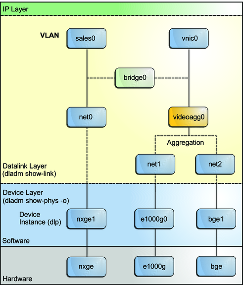
On the datalink layer of the same network stack implementation, you can configure bridges as shown in the following figure. Two interfaces, net0 and videoagg0, are configured as a bridge, bridge0. Packets that are received on one interface are forwarded to the other interface. After bridge configuration, both interfaces can still be used to configure VLANs and IP interfaces.
Figure 1-3 Bridges in the Network Stack for Oracle Solaris 11

Bridges and bridge configuration are discussed in Chapter 4, Administering Bridged Networks (Tasks), in Managing Oracle Solaris 11.1 Network Performance .